Dynomotion

Group: DynoMotion Message: 6744 From: David Beardsley Date: 2/16/2013
Subject: Trajectory Planner Setup in KmotionCNC

Hi DynoMotion Members !

In my introductory post some weeks back I shared that I’ve been using my machine to cut rapid proto-molds for the UAV industry. I've been having good luck and my customers are happy. However, I’ve been chasing an issue with configuring the trajectory planner since day one. Although I've studied the info on the site, I still don’t have a firm grasp on how the numbers influence reality.

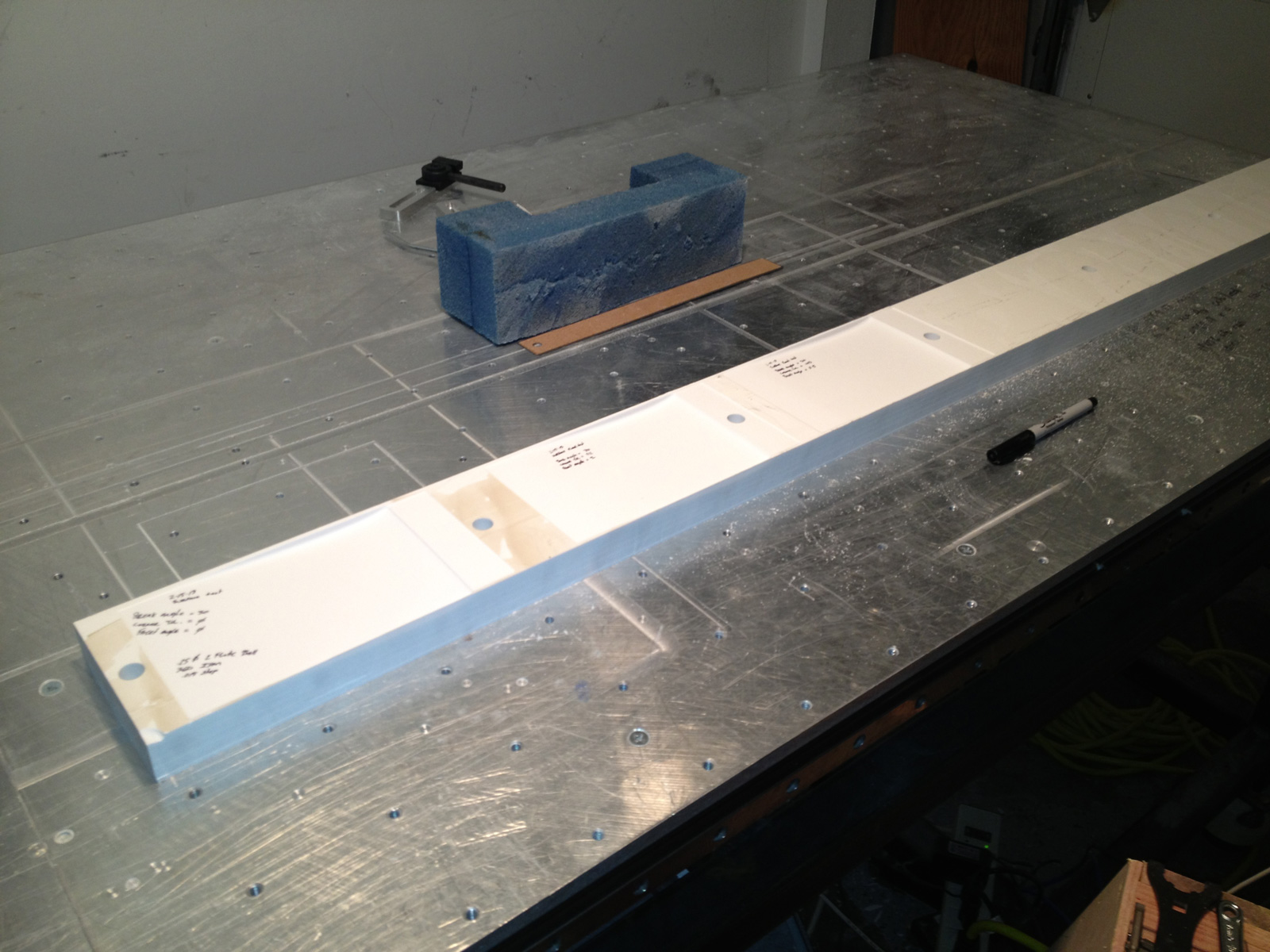
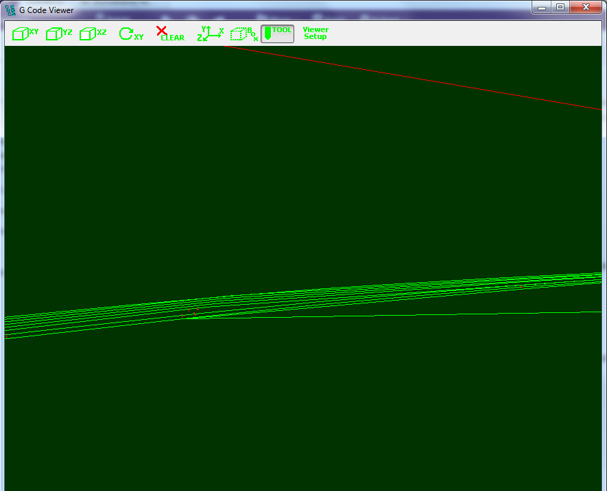
Attached are photos I took of a test I ran today.

Here is my setup details

Material = a Corian type solid surface material
IPM = 360
Cutter = Harvey Tool, 0.25” 2 flute HS Plastic
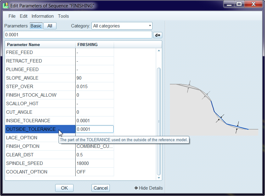
Step over = 0.015
Finish pass depth of cut = .025

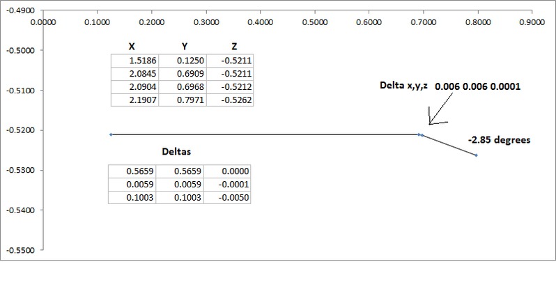
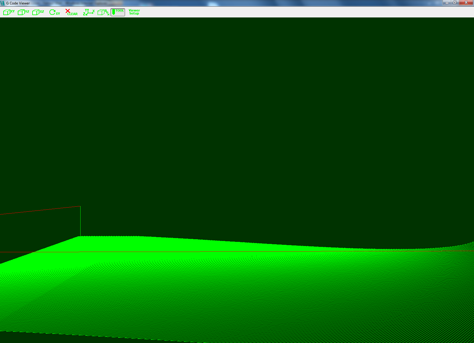
The attached images show the issues I’m seeing very clearly. Changing the settings in the trajectory planner is having a huge effect on my geometry. The scary part is, the result is as if my machine is not cutting the Gcode I programmed…  I know this is because I don't understanding what’s happening – but it freaks me out to think what I programmed isn't what I’m getting…
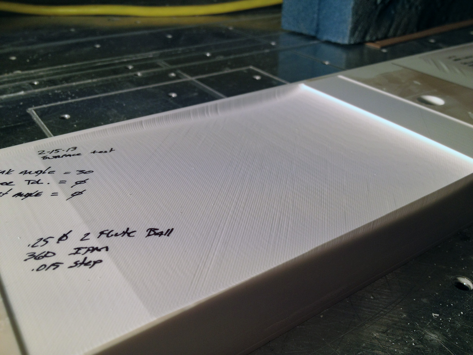
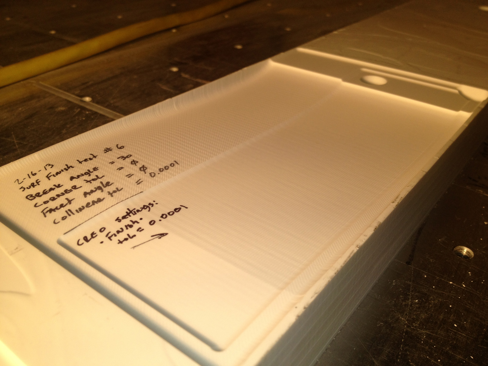
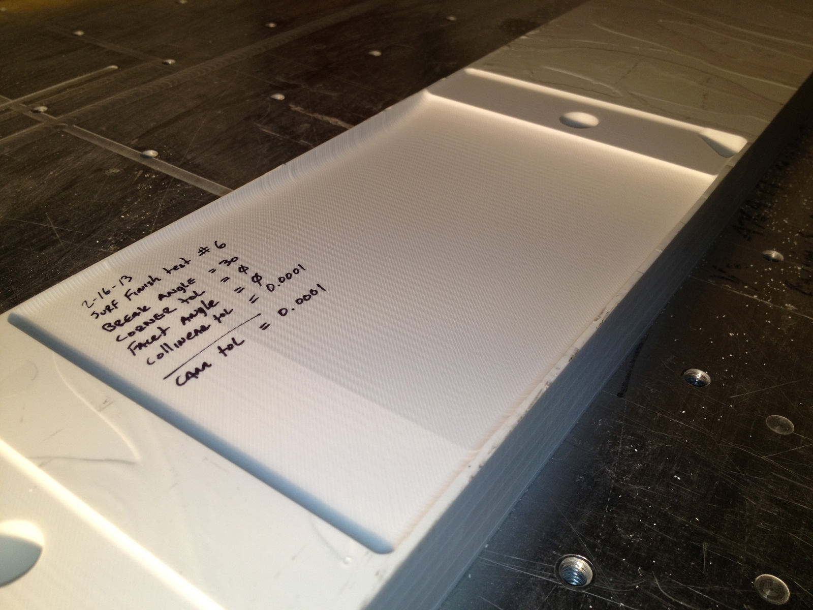
Surf_finish_1

Break Angle = 30
Corner Tolerance = 0
Facet Angle = 0

This is how I’ve been cutting all my parts as a work-around since I couldn't get the trajectory planner setup correctly. With these settings, I’d thought I’d effectively turned the trajectory planner off. The surface finish is “ok”, but you can still see areas where the cutter passes slightly deeper for no apparent reason.
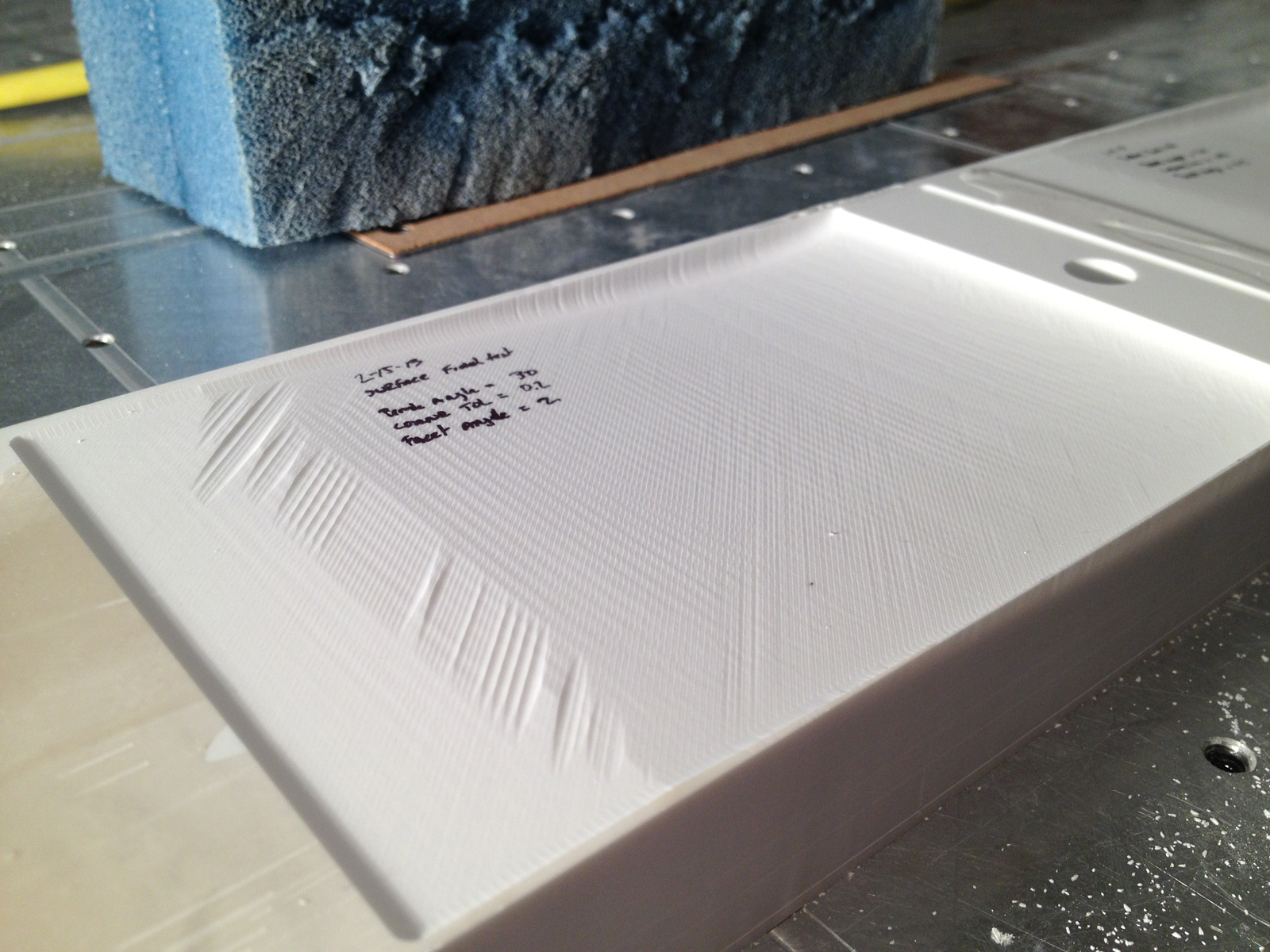
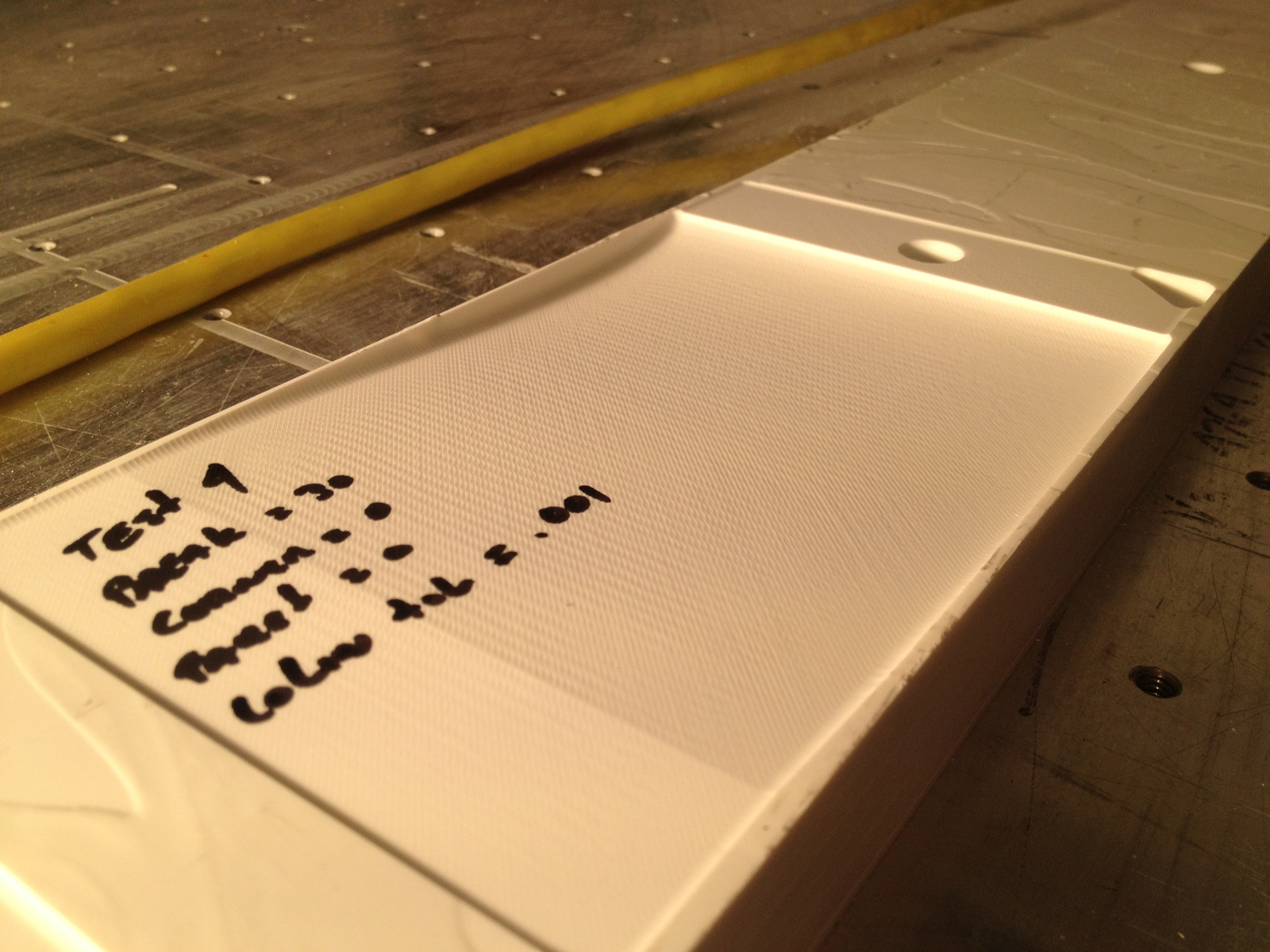
Surf_finish_2

Break Angle = 30
Corner Tolerance = 0.2
Facet Angle = 2

This cut was done with the settings that were in the planner when I first took delivery of the machine. In this photo you can see how the resulting cuts are radically wrong and the part is ruined.
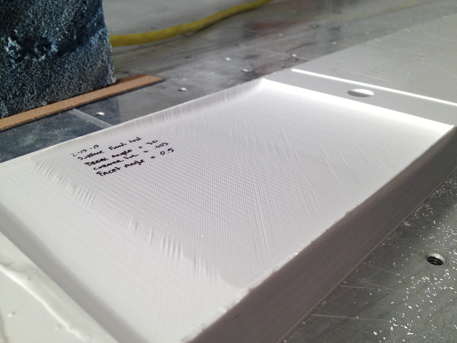
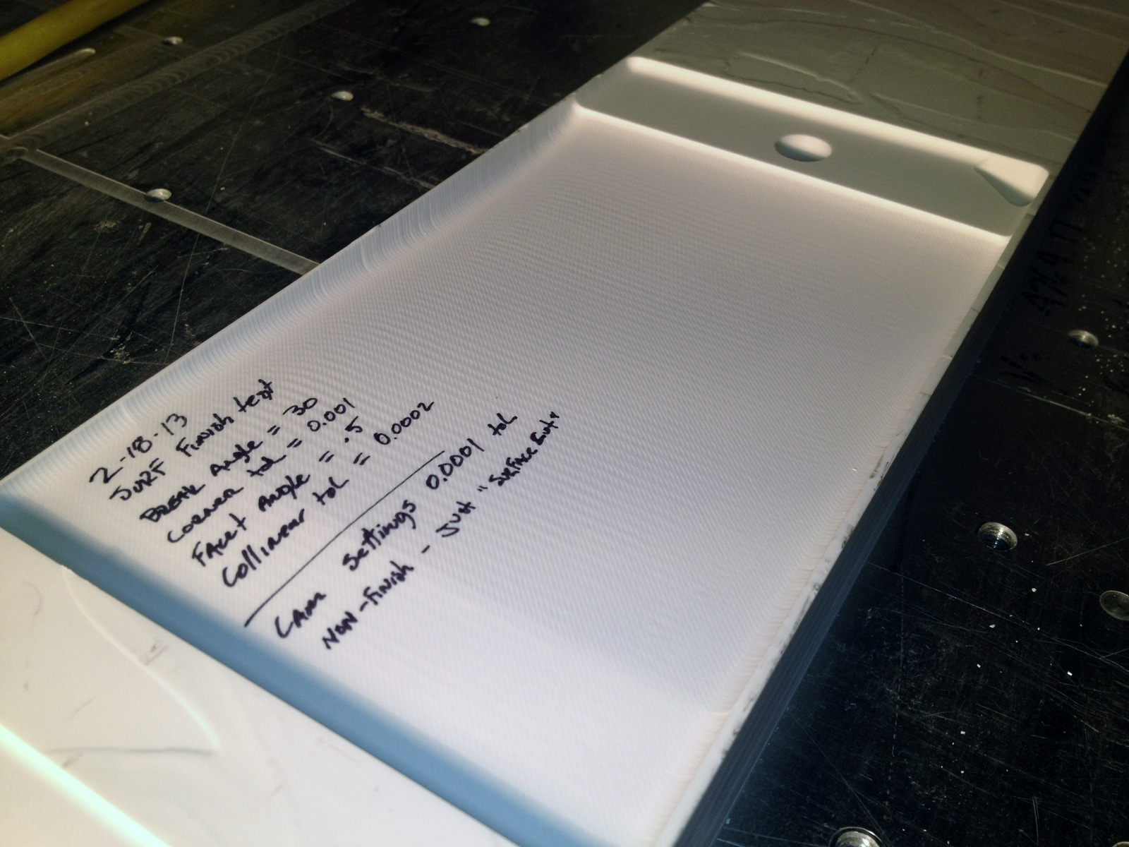
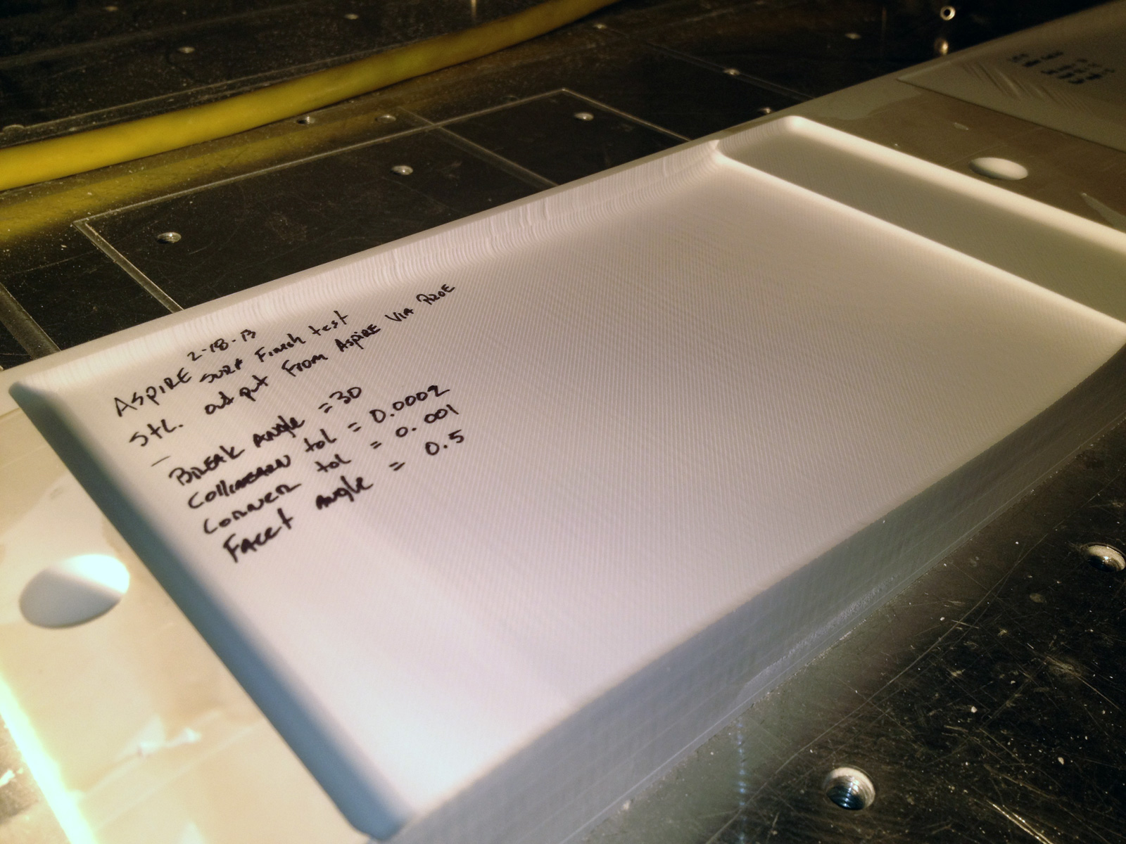
Surf_finish_3
Break Angle = 30
Corner Tolerance = 0.003
Facet Angle = 0.5

This cut is better than #2, but still not acceptable finish quality.


I’m hoping someone can review the attached photos and give me some pointers on what I’m doing wrong. I need to configure the trajectory planner correctly for the best surface finish my machine is capable of. Keep in mind, most of my geometry is airfoil shapes. The challenge is the curve angle is very low (less than 10deg) as the airfoil approaches the trailing edge of the wing, while its very high (almost 90deg) at the leading edge.

A side note on overall machine flex / stiffness / ring…
I also cut many photo lithophones using a 0.03125 cutter with a .003 step. The finish is AMAZING! I use the trajectory planner settings that are used in photo “Surf_Finish_1" and never see any of these issues. While the machine isn't a 250K VMC, its pretty darn stiff with little ring and little flex.

thanks in advance for any help!

Dave

  @@attachment@@
Group: DynoMotion Message: 6745 From: Tom Kerekes Date: 2/16/2013
Subject: Re: Trajectory Planner Setup in KmotionCNC [4 Attachments]
Hi David,

That certainly looks horrible.

Could you post all your Trajectory Planner settings?   Collinear Tolerance, Accelerations, Velocities, Resolution.  Or just post the GCodeConfigCNC.txt file?

What Version of KMotion are you using?

Also could you post the GCode or some interesting sections of it?  And the Feed Rate (always 360ipm) ?

I assume this is a Servo System?

I would think that Suf_finish_3 setting should work if the GCode is reasonable.

surf_finish_1 should not really work well.  That is saying it is ok to go through 30 degree corners without any rounding or stopping.  But if your Gcode is relatively smooth it might be ok.

surf_finish_2 is allowing 0.2 inch deviations from paths so that could be bad.

Please post the requested info.  I have no doubt we can improve things.

Regards
TK


Group: DynoMotion Message: 6746 From: Dave - Gmail Date: 2/16/2013
Subject: Re: Trajectory Planner Setup in KmotionCNC
Hey Tom -

Thanks for the quick reply. I'm at my sons soccer game, but will attach all files as soon as I get home.

All my CAD and CAM dev work is done in Creo2. The settings for tolerance in the files are very high - as it's the same as I use for the HAAS and Daytron at work. That's probably why #1 looks the best, it's smooth gcode.

I always run at 400-600 ipm. My system has encoders and I've done all the math and double checking to ensure I'm holding better than 2 thou at the motor. I've done some scanning and metrology comparing previous cuts to my cad files and I'm confident my overall accuracy is acceptable (except when using the setting shown in 2 or 3)

Thanks,
Dave

I'm almost 100% sure this is user error based on my lack of understanding on how the trajectory planner works. 

On Feb 16, 2013, at 6:01 PM, Tom Kerekes <tk@...> wrote:


Hi David,

That certainly looks horrible.

Could you post all your Trajectory Planner settings?   Collinear Tolerance, Accelerations, Velocities, Resolution.  Or just post the GCodeConfigCNC.txt file?

What Version of KMotion are you using?

Also could you post the GCode or some interesting sections of it?  And the Feed Rate (always 360ipm) ?

I assume this is a Servo System?

I would think that Suf_finish_3 setting should work if the GCode is reasonable.

surf_finish_1 should not really work well.  That is saying it is ok to go through 30 degree corners without any rounding or stopping.  But if your Gcode is relatively smooth it might be ok.

surf_finish_2 is allowing 0.2 inch deviations from paths so that could be bad.

Please post the requested info.  I have no doubt we can improve things.

Regards
TK


Group: DynoMotion Message: 6747 From: David Beardsley Date: 2/16/2013
Subject: Re: Trajectory Planner Setup in KmotionCNC
My gcode and config file are attached.

Both the code and the config are the same as I've used for the last 3 projects I've shipped. These are the settings used for surf_finish_1. Let me know what you think.

This is not a servo system. This is a stepper system. 

thanks!
Dave 


On Sat, Feb 16, 2013 at 6:29 PM, Dave - Gmail <dabeardsley@...> wrote:
Hey Tom -

Thanks for the quick reply. I'm at my sons soccer game, but will attach all files as soon as I get home.

All my CAD and CAM dev work is done in Creo2. The settings for tolerance in the files are very high - as it's the same as I use for the HAAS and Daytron at work. That's probably why #1 looks the best, it's smooth gcode.

I always run at 400-600 ipm. My system has encoders and I've done all the math and double checking to ensure I'm holding better than 2 thou at the motor. I've done some scanning and metrology comparing previous cuts to my cad files and I'm confident my overall accuracy is acceptable (except when using the setting shown in 2 or 3)

Thanks,
Dave

I'm almost 100% sure this is user error based on my lack of understanding on how the trajectory planner works. 

On Feb 16, 2013, at 6:01 PM, Tom Kerekes <tk@...> wrote:


Hi David,

That certainly looks horrible.

Could you post all your Trajectory Planner settings?   Collinear Tolerance, Accelerations, Velocities, Resolution.  Or just post the GCodeConfigCNC.txt file?

What Version of KMotion are you using?

Also could you post the GCode or some interesting sections of it?  And the Feed Rate (always 360ipm) ?

I assume this is a Servo System?

I would think that Suf_finish_3 setting should work if the GCode is reasonable.

surf_finish_1 should not really work well.  That is saying it is ok to go through 30 degree corners without any rounding or stopping.  But if your Gcode is relatively smooth it might be ok.

surf_finish_2 is allowing 0.2 inch deviations from paths so that could be bad.

Please post the requested info.  I have no doubt we can improve things.

Regards
TK


Group: DynoMotion Message: 6752 From: Tom Kerekes Date: 2/17/2013
Subject: Re: Trajectory Planner Setup in KmotionCNC [2 Attachments]
Hi Dave,

I think I understand what is going on.  It is fairly complicated and difficult to explain with multiple causes.  Basically there are cases where "Corner Rounding" is applied to the full amount that you are allowing, and cases where it is not.  I believe the issue is mainly with the GCode and Trajectory Planning rather than with the mechanics.  Although it may be that something mechanical also adds to the effect. 

With a Trajectory Planner Corner Rounding Setting of 3 mils the Trajectory planner is given permission to deviate from the original GCode Path by up to 3 mils to insert a curve.  But it doesn't necessarily always deviate by 3 mils.  A relatively long curve is required to deviate 3 mils for such a shallow angle.  To fit a long curve two long GCode segments are required. 

In your GCode example the problem area is where there is a fairly flat plateau which then enters a sudden, but shallow, angle downward into a curve.  In your Surf_finish_3 example sometimes the angle is rounded and sometimes it isn't.  Your pictures are not very clear but I'm guessing those may be ~3mil variations causing the uglyness.

If you zoom and rotate just right I can see the variations in the plot on the GCode Viewer.  You must run the Job for the GCode Viewer to display the actual Trajectory Planned result.  Simulation mode only plots the raw GCode.  But that makes it nice to see the difference.

Here Are some things I noticed:

#1 - The original raw GCode does have some small irregularities - I'm guessing they are ~ 1mil in amplitude
#2 - Specifying only 4 decimal digits adds 0.1 mil of noise to the paths.  Is there a way you can output more digits?
#3 - The CAD system typically puts a tiny ~6 mil long segment right at the angle for some reason.
#4 - The Collinear Tolerance setting is very small at 0.1mil.  Being right at the noise level in the data causes random combinations of segments that should be collinear.
#5 - The amount of corner rounding varies dependent on the above.

I've attached a GCode fragment from what you sent me that shows several scans with a large amount of variation.  Also a GCode Viewer plot which shows the small but significant variation with your Surf_finish_3 settings selected.  And a diagram to help explain what is happening.

I don't really have a clear solution, but there are a few things to try.  It is always best to fix any issues with the GCode first (Items #1 #2 #3 above).

One thing to decide first would be whether we want to work toward always rounding the corner by 3 mils, or never rounding the corner by 3 mils.  In order to always round the corner we would need to make the Gcode as smooth and noise free as possible and then specify a larger Collinear Tolerance so that there will be long straight segments on the entry and exit of the Angle.  To never round the corner we could probably just reduce the Corner Rounding Tolerance.

Any thoughts?

Regards
TK


Group: DynoMotion Message: 6756 From: David Beardsley Date: 2/17/2013
Subject: Re: Trajectory Planner Setup in KmotionCNC [3 Attachments]
Hi Tom - 

thanks for the info - and searching for a solution....

I've attached a few files for review. These are some of the output options in my CAM software  I agree that shipping the cleanest code to the controller is the best option..... once we've determined the code is as clean as possible, then we can chase other issues.

The milprm.mil file shows all the options available for a surface cut. you can open it as a regular txt file. I included it for reference as I don't know exactly what all the options mean, or how best to explain them. The other 2 images seem like they are closer to what we are after. What tolerance would you recommend I use?

Would you be up for a screen share via gotomeeting? I could show you my settings live - with the context of the CAD model in session some of the options might make more sense to you than me...

Carl tells me you know something about Zcorp / 3D Systems? I know those guys well. Got an old Zcorp 510 just down the hall :)


On Sun, Feb 17, 2013 at 4:13 PM, Tom Kerekes <tk@...> wrote:
 
[Attachment(s) from Tom Kerekes included below]

Hi Dave,

I think I understand what is going on.  It is fairly complicated and difficult to explain with multiple causes.  Basically there are cases where "Corner Rounding" is applied to the full amount that you are allowing, and cases where it is not.  I believe the issue is mainly with the GCode and Trajectory Planning rather than with the mechanics.  Although it may be that something mechanical also adds to the effect. 

With a Trajectory Planner Corner Rounding Setting of 3 mils the Trajectory planner is given permission to deviate from the original GCode Path by up to 3 mils to insert a curve.  But it doesn't necessarily always deviate by 3 mils.  A relatively long curve is required to deviate 3 mils for such a shallow angle.  To fit a long curve two long GCode segments are required. 

In your GCode example the problem area is where there is a fairly flat plateau which then enters a sudden, but shallow, angle downward into a curve.  In your Surf_finish_3 example sometimes the angle is rounded and sometimes it isn't.  Your pictures are not very clear but I'm guessing those may be ~3mil variations causing the uglyness.

If you zoom and rotate just right I can see the variations in the plot on the GCode Viewer.  You must run the Job for the GCode Viewer to display the actual Trajectory Planned result.  Simulation mode only plots the raw GCode.  But that makes it nice to see the difference.

Here Are some things I noticed:

#1 - The original raw GCode does have some small irregularities - I'm guessing they are ~ 1mil in amplitude
#2 - Specifying only 4 decimal digits adds 0.1 mil of noise to the paths.  Is there a way you can output more digits?
#3 - The CAD system typically puts a tiny ~6 mil long segment right at the angle for some reason.
#4 - The Collinear Tolerance setting is very small at 0.1mil.  Being right at the noise level in the data causes random combinations of segments that should be collinear.
#5 - The amount of corner rounding varies dependent on the above.

I've attached a GCode fragment from what you sent me that shows several scans with a large amount of variation.  Also a GCode Viewer plot which shows the small but significant variation with your Surf_finish_3 settings selected.  And a diagram to help explain what is happening.

I don't really have a clear solution, but there are a few things to try.  It is always best to fix any issues with the GCode first (Items #1 #2 #3 above).

One thing to decide first would be whether we want to work toward always rounding the corner by 3 mils, or never rounding the corner by 3 mils.  In order to always round the corner we would need to make the Gcode as smooth and noise free as possible and then specify a larger Collinear Tolerance so that there will be long straight segments on the entry and exit of the Angle.  To never round the corner we could probably just reduce the Corner Rounding Tolerance.

Any thoughts?

Regards
TK


Group: DynoMotion Message: 6758 From: Tom Kerekes Date: 2/18/2013
Subject: Re: Trajectory Planner Setup in KmotionCNC [3 Attachments]
Hi Dave,

I'm not familiar with that CAM software so I can't really help.  Maybe just experiment with the Tolerance.  Maybe 0.1mil or 0.3mils.  It will probably make the GCode much bigger but disk space is cheap.  I didn't see anywhere to change the number of digits in the output.  Maybe that is in your "post" settings?   0.1 mils of noise doesn't sound like much but especially with short vectors that can relate to significant changes in direction at rapid rates.

Regarding 3D Systems: I've worked on a lot of their motion control over many years.  Really cool stuff.  Laser scanning (Stereo Lithography and Laser Sintering) involves complex trajectories at really high speeds and high accuracy (sub-mil at thousands of ips).   3D just bought Zcorp so I get to work with those guys now also.  Did you note that Obama mentioned 3D printing in his state of the union address?

Regards
TK

Group: DynoMotion Message: 6763 From: David Beardsley Date: 2/18/2013
Subject: Re: Trajectory Planner Setup in KmotionCNC
Attachments :
Hi Tom - 

sorry to keep bugging you on this one....

Attached is a new output from my CAM software for the same geometry. I changed the tolerance from 0.001 to 0.0001. I also changed the line segment connection type to straight from curved. 

I'm not sure I understood how to review the data for noise using the gview as you showed in your previously attached screen shot. Can you take a look at this code and see if its clean enough not to barf the trajectory planner? If it is better, what settings should I try in the trajectory planner to smooth out the motion?

thanks!
Dave


On Mon, Feb 18, 2013 at 8:44 AM, Tom Kerekes <tk@...> wrote:
 

Hi Dave,

I'm not familiar with that CAM software so I can't really help.  Maybe just experiment with the Tolerance.  Maybe 0.1mil or 0.3mils.  It will probably make the GCode much bigger but disk space is cheap.  I didn't see anywhere to change the number of digits in the output.  Maybe that is in your "post" settings?   0.1 mils of noise doesn't sound like much but especially with short vectors that can relate to significant changes in direction at rapid rates.

Regarding 3D Systems: I've worked on a lot of their motion control over many years.  Really cool stuff.  Laser scanning (Stereo Lithography and Laser Sintering) involves complex trajectories at really high speeds and high accuracy (sub-mil at thousands of ips).   3D just bought Zcorp so I get to work with those guys now also.  Did you note that Obama mentioned 3D printing in his state of the union address?

Regards
TK

Group: DynoMotion Message: 6766 From: Tom Kerekes Date: 2/18/2013
Subject: Re: Trajectory Planner Setup in KmotionCNC [1 Attachment]
Hi Dave,

NP I find this interesting.

I've plotted the before and after Raw GCode.   I can see a significant difference and the GCode only ~ doubled in size.  See the Before/After GCode Viewer plots attached.  Of course we are looking for like 1 mil noise on a ~3 inch part so it works out to less than a screen pixel, but you can still see the difference.

You still only have 4 decimal digits and that tiny segment just at the angle point is still there for some reason.  I plotted a typical tiny segment with a distorted scale to give some perspective.  See attached.  This one is 6mils in x, 6 mils in y, and 0.1mils in z.   Which is at a less steep angle than the general slope.  1/60 vs 1/200.   Anyway setting the Collinear Tolerance to 0.0002 will allow this vector to be combined and then the corner will be rounded.

The general slope in that region goes to about -2.85 degrees.  If I did the math right I think it turns out a 3 inch radius curve can be inserted and only give a 1 mil deviation in the corner and will still allow nearly full speed 300ipm operation through the curve using your 8 in/sec2 acceleration.

So in summary maybe try parameters:

Break Angle 30
Collinear Tolerance 0.0002
Corner Tol 0.001
Facet angle 0.5

Regards
TK
Group: DynoMotion Message: 6769 From: David Beardsley Date: 2/18/2013
Subject: Re: Trajectory Planner Setup in KmotionCNC [3 Attachments]
Hey Tom - 

wow - you've torn into this thing! Very cool - I'm learning - and that's the most important part for me!

Some significant findings today. Please see the attached images.

As you suspected, the cleaner (tighter) gCode had a large impact. I'd thought I was using the same settings as at work, but I wasn't. I called Carl on the drive in and told him I was gona race down to the shop as soon as I got to work and verify. that's when I found that we are using 0.0001 as our default out of WorkNC for the Daytron.

I reset my CAM settings in Creo2 to match, and re-processed the same file (that's what I sent you this morning). At the same time you were crunching math, I started cutting more tests. After looking at the results I'm probably at the limit of the machine stiffness / resonance.  I'm planning to cut a reference piece on the Daytron for comparison. I'm expecting it will look better.... but not $275,000 better :)

I'm also starting to think Creo2 isn't processing the code as well as WorkNC, MasterCam, or Surfcam. I don't have those packages at home, but I plan to cut the same Daytron reference code on my machine just to see the difference  I do have a current copy of Aspire that can write code over an STL, so I processed my solid geometry to an STL with max deviation of 0.001. I'll cut that too - just to see if the Aspire algorithms do a better job than Creo. Its a much simpler tool - but seems to do a great job with code.

OK - onto the images

Test #4: (same gCode I sent you this morning)
Settings:
  • Break = 30
  • Collinear Tol = 0.001
  • Corner Tol = 0
  • Facet Angle = 0

Test #5: (same gCode I sent you this morning)
Settings:
  • Break = 30
  • Collinear Tol = 0.0001 (to match CAM software)
  • Corner Tol = 0
  • Facet Angle = 0

Test #6: Using different settings than I'd been using. This is called a "finish cut". The Finish Cut option allows the user to select an inside and outside tolerance (see image). I think this effectively averages the error. I couldn't figure out how to do a 45deg scan-line using this option. I think this is the best result.
Settings:
  • Break = 30
  • Collinear Tol = 0.0001 (to match CAM software)
  • Corner Tol = 0
  • Facet Angle = 0

Test #7: (same gCode I sent you this morning) - using your settings suggested in your last e-mail
Settings: 
  • Break = 30
  • Collinear Tol = 0.0002 (to match CAM software)
  • Corner Tol = 0.001
  • Facet Angle = 0.5

The end result of all this....
I think the crazy variation in depth per scan line is effectively gone now, using a few different options. I still see some "waves" in the cut, but they are totally consistent - I expect these might be mechanics related.

I'd like to keep chasing this until I'm 100% sure I've reached the limits of the mechanics. Carl and I have a new machine in the works now - effectively a redneck Daytron. I expect that will give me MUCH sexier results.

thanks again for all your help!
Dave


On Mon, Feb 18, 2013 at 4:36 PM, Tom Kerekes <tk@...> wrote:
 
[Attachment(s) from Tom Kerekes included below]

Hi Dave,

NP I find this interesting.

I've plotted the before and after Raw GCode.   I can see a significant difference and the GCode only ~ doubled in size.  See the Before/After GCode Viewer plots attached.  Of course we are looking for like 1 mil noise on a ~3 inch part so it works out to less than a screen pixel, but you can still see the difference.

You still only have 4 decimal digits and that tiny segment just at the angle point is still there for some reason.  I plotted a typical tiny segment with a distorted scale to give some perspective.  See attached.  This one is 6mils in x, 6 mils in y, and 0.1mils in z.   Which is at a less steep angle than the general slope.  1/60 vs 1/200.   Anyway setting the Collinear Tolerance to 0.0002 will allow this vector to be combined and then the corner will be rounded.

The general slope in that region goes to about -2.85 degrees.  If I did the math right I think it turns out a 3 inch radius curve can be inserted and only give a 1 mil deviation in the corner and will still allow nearly full speed 300ipm operation through the curve using your 8 in/sec2 acceleration.

So in summary maybe try parameters:

Break Angle 30
Collinear Tolerance 0.0002
Corner Tol 0.001
Facet angle 0.5

Regards
TK
Group: DynoMotion Message: 6770 From: David Beardsley Date: 2/18/2013
Subject: Re: Trajectory Planner Setup in KmotionCNC [5 Attachments]
Hi Tom - 

I wish I could say I'm surprised, but my suspicions were just confirmed. The $1800.00 Aspire gCode seems to be much cleaner than whats being output from 20K+ Creo software. Ugh!

Truth is, I'm not that shocked. The full-on machining packages are very complex! I'm sure I don't know enough of what I'm doing to tweak all the settings just perfectly. Aspire is super stripped down and simple - thus less chance for a user (like me) to mess it up.

Attached is the image and gCode for Test #7: (STL output from Creo - Max deviation 0.001, Imported into Aspire) All other settings the same (IPM, Cutter, Depth, etc)
  • Break = 30
  • Collinear Tol = 0.0002 (to match CAM software)
  • Corner Tol = 0.001
  • Facet Angle = 0.5
This also gives me hope that the gCode I plan to complete at work (using WorkNC for the Daytron) might be even better - if it is, then I guess its off to WorkNC class :)

thanks again for your help!
Dave

BTW: I'm noticing the forum is down sizing my photos drastically  If you care to see the original higher res images I could make them available via .zip from my FTP server.


On Mon, Feb 18, 2013 at 7:18 PM, David Beardsley <dabeardsley@...> wrote:
 
[Attachment(s) from David Beardsley included below]

Hey Tom - 

wow - you've torn into this thing! Very cool - I'm learning - and that's the most important part for me!

Some significant findings today. Please see the attached images.

As you suspected, the cleaner (tighter) gCode had a large impact. I'd thought I was using the same settings as at work, but I wasn't. I called Carl on the drive in and told him I was gona race down to the shop as soon as I got to work and verify. that's when I found that we are using 0.0001 as our default out of WorkNC for the Daytron.

I reset my CAM settings in Creo2 to match, and re-processed the same file (that's what I sent you this morning). At the same time you were crunching math, I started cutting more tests. After looking at the results I'm probably at the limit of the machine stiffness / resonance.  I'm planning to cut a reference piece on the Daytron for comparison. I'm expecting it will look better.... but not $275,000 better :)

I'm also starting to think Creo2 isn't processing the code as well as WorkNC, MasterCam, or Surfcam. I don't have those packages at home, but I plan to cut the same Daytron reference code on my machine just to see the difference  I do have a current copy of Aspire that can write code over an STL, so I processed my solid geometry to an STL with max deviation of 0.001. I'll cut that too - just to see if the Aspire algorithms do a better job than Creo. Its a much simpler tool - but seems to do a great job with code.

OK - onto the images

Test #4: (same gCode I sent you this morning)
Settings:
  • Break = 30
  • Collinear Tol = 0.001
  • Corner Tol = 0
  • Facet Angle = 0

Test #5: (same gCode I sent you this morning)
Settings:
  • Break = 30
  • Collinear Tol = 0.0001 (to match CAM software)
  • Corner Tol = 0
  • Facet Angle = 0

Test #6: Using different settings than I'd been using. This is called a "finish cut". The Finish Cut option allows the user to select an inside and outside tolerance (see image). I think this effectively averages the error. I couldn't figure out how to do a 45deg scan-line using this option. I think this is the best result.
Settings:
  • Break = 30
  • Collinear Tol = 0.0001 (to match CAM software)
  • Corner Tol = 0
  • Facet Angle = 0

Test #7: (same gCode I sent you this morning) - using your settings suggested in your last e-mail
Settings: 
  • Break = 30
  • Collinear Tol = 0.0002 (to match CAM software)
  • Corner Tol = 0.001
  • Facet Angle = 0.5

The end result of all this....
I think the crazy variation in depth per scan line is effectively gone now, using a few different options. I still see some "waves" in the cut, but they are totally consistent - I expect these might be mechanics related.

I'd like to keep chasing this until I'm 100% sure I've reached the limits of the mechanics. Carl and I have a new machine in the works now - effectively a redneck Daytron. I expect that will give me MUCH sexier results.

thanks again for all your help!
Dave


On Mon, Feb 18, 2013 at 4:36 PM, Tom Kerekes <tk@...> wrote:
 
[Attachment(s) from Tom Kerekes included below]

Hi Dave,

NP I find this interesting.

I've plotted the before and after Raw GCode.   I can see a significant difference and the GCode only ~ doubled in size.  See the Before/After GCode Viewer plots attached.  Of course we are looking for like 1 mil noise on a ~3 inch part so it works out to less than a screen pixel, but you can still see the difference.

You still only have 4 decimal digits and that tiny segment just at the angle point is still there for some reason.  I plotted a typical tiny segment with a distorted scale to give some perspective.  See attached.  This one is 6mils in x, 6 mils in y, and 0.1mils in z.   Which is at a less steep angle than the general slope.  1/60 vs 1/200.   Anyway setting the Collinear Tolerance to 0.0002 will allow this vector to be combined and then the corner will be rounded.

The general slope in that region goes to about -2.85 degrees.  If I did the math right I think it turns out a 3 inch radius curve can be inserted and only give a 1 mil deviation in the corner and will still allow nearly full speed 300ipm operation through the curve using your 8 in/sec2 acceleration.

So in summary maybe try parameters:

Break Angle 30
Collinear Tolerance 0.0002
Corner Tol 0.001
Facet angle 0.5

Regards
TK
Group: DynoMotion Message: 6773 From: Tom Kerekes Date: 2/19/2013
Subject: Re: Trajectory Planner Setup in KmotionCNC [2 Attachments]
Hi Dave,

Looks better to me.

I wonder what the "waves" are in the X direction.  If it were vibration or resonance I would expect it to be spatially consistent but rather time dependent.  Or is that just from a prior rough cut or something? 

Anyway thanks for sharing.

Regards
TK 

Group: DynoMotion Message: 6776 From: Dave - Gmail Date: 2/19/2013
Subject: Re: Trajectory Planner Setup in KmotionCNC
Ya - I wonder the same thing... Your probably right. That's the type of stuff I need to iron out. Problem is I have no clue what's causing it?

I'm not even sure where to start. Ill try the WorkNC code for the Daytron next. Maybe it's just the code? Who knows - could be the cutter? Or even the material? Ugh!!

Thanks again for your help. Any other pointers on the "wave effect" would be great - ill take'em!

Thanks!
Dave

On Feb 19, 2013, at 11:34 AM, Tom Kerekes <tk@...> wrote:


Hi Dave,

Looks better to me.

I wonder what the "waves" are in the X direction.  If it were vibration or resonance I would expect it to be spatially consistent but rather time dependent.  Or is that just from a prior rough cut or something? 

Anyway thanks for sharing.

Regards
TK 

Group: DynoMotion Message: 6777 From: Tom Kerekes Date: 2/20/2013
Subject: Re: Trajectory Planner Setup in KmotionCNC
Hi Dave,

One obvious test would be to build two parts side by side using the same GCode for each.  Maybe separated in Y and shifted an inch in X (If I understand your axis's directions).

If the "waves" line up line up relative to the machine then they are likely a function of the machine (Guide rails?).

If the "waves" in each part come out the same the they are likely related to the data.

Good luck
TK

Group: DynoMotion Message: 6778 From: Dave - Gmail Date: 2/20/2013
Subject: Re: Trajectory Planner Setup in KmotionCNC
Ahhh yes... Such a simple test - I should have figured that one out myself!

Ill test and see what I get

On Feb 20, 2013, at 5:04 PM, Tom Kerekes <tk@...> wrote:


Hi Dave,

One obvious test would be to build two parts side by side using the same GCode for each.  Maybe separated in Y and shifted an inch in X (If I understand your axis's directions).

If the "waves" line up line up relative to the machine then they are likely a function of the machine (Guide rails?).

If the "waves" in each part come out the same the they are likely related to the data.

Good luck
TK